Wirebuzz: A simple cable continuity tester
Continuity testers are very useful tools, especially when you need to find where a cable goes (if you have multiple cables) or to verify the integrity of the cable. This continuity tester was made for the sole purpose of testing long cables and it is not suitable for some components because it uses 12v so that it can be able to test long cables.
Parts
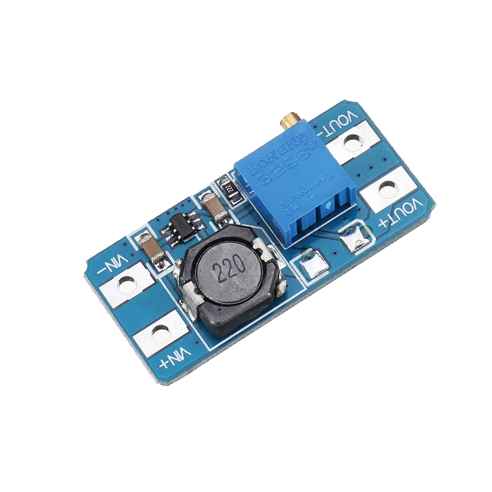

- Buck-Boost converter: I used a buck boost converter to increase the battery voltage to 12v.
- TP4056 Charge controller: A simple charge controller for the 18650 battery.
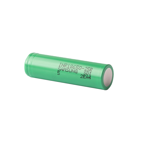
- 18650: Any 18650 will do, i salvaged one from an old laptop battery. I tested it first and it is performing adequately.
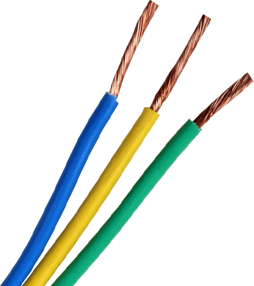
- Wires: I used speaker wires for the test leads, for the rest of the cables i used 28AWG wires.
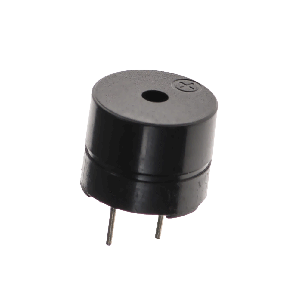
- Buzzer: i used a 5v buzzer. As an experiment i tried slowly increasing the voltage until 12V, surprisingly it run without a problem. I would recommend using a 12V buzzer or a current limiting resistor.
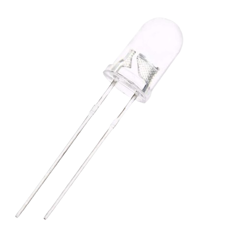
- Leds: A 5mm green LED for the continuity indicator and a 3mm red LED as a power indicator.
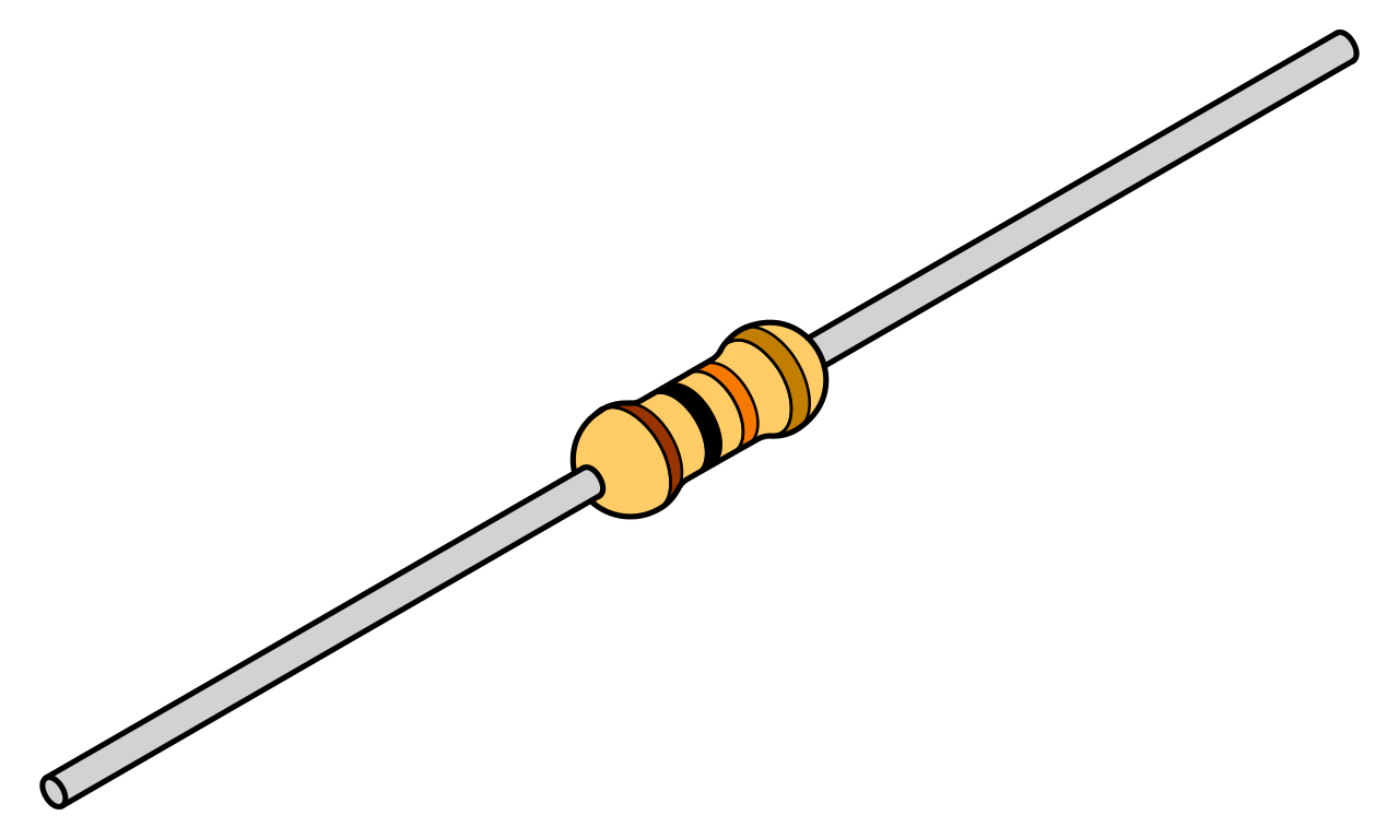
- Ressistors: A 1.2 Kohm resistor for the power LED and a 1Kohm resistor for the continuity LED. Values might vary depending on the LED that you use.
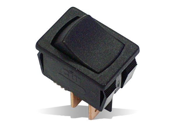
- Switch: I used a small SPST rocker switch, i really like those switches.
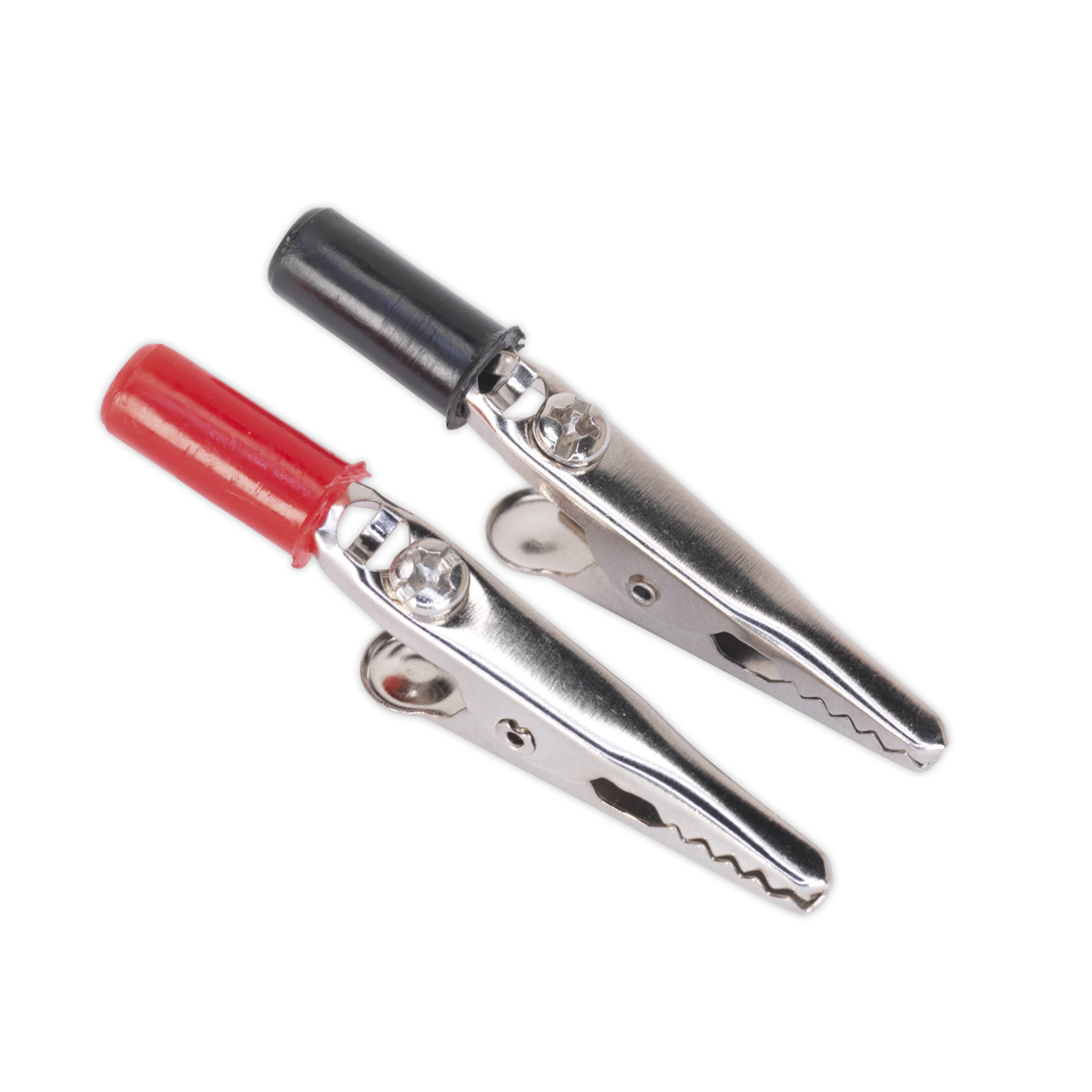
- Crocodile clips: I used a pair of simple cheap crocodile clips, feel free to use something fancier if you want.
Tools
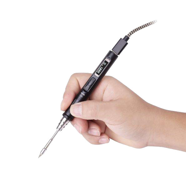
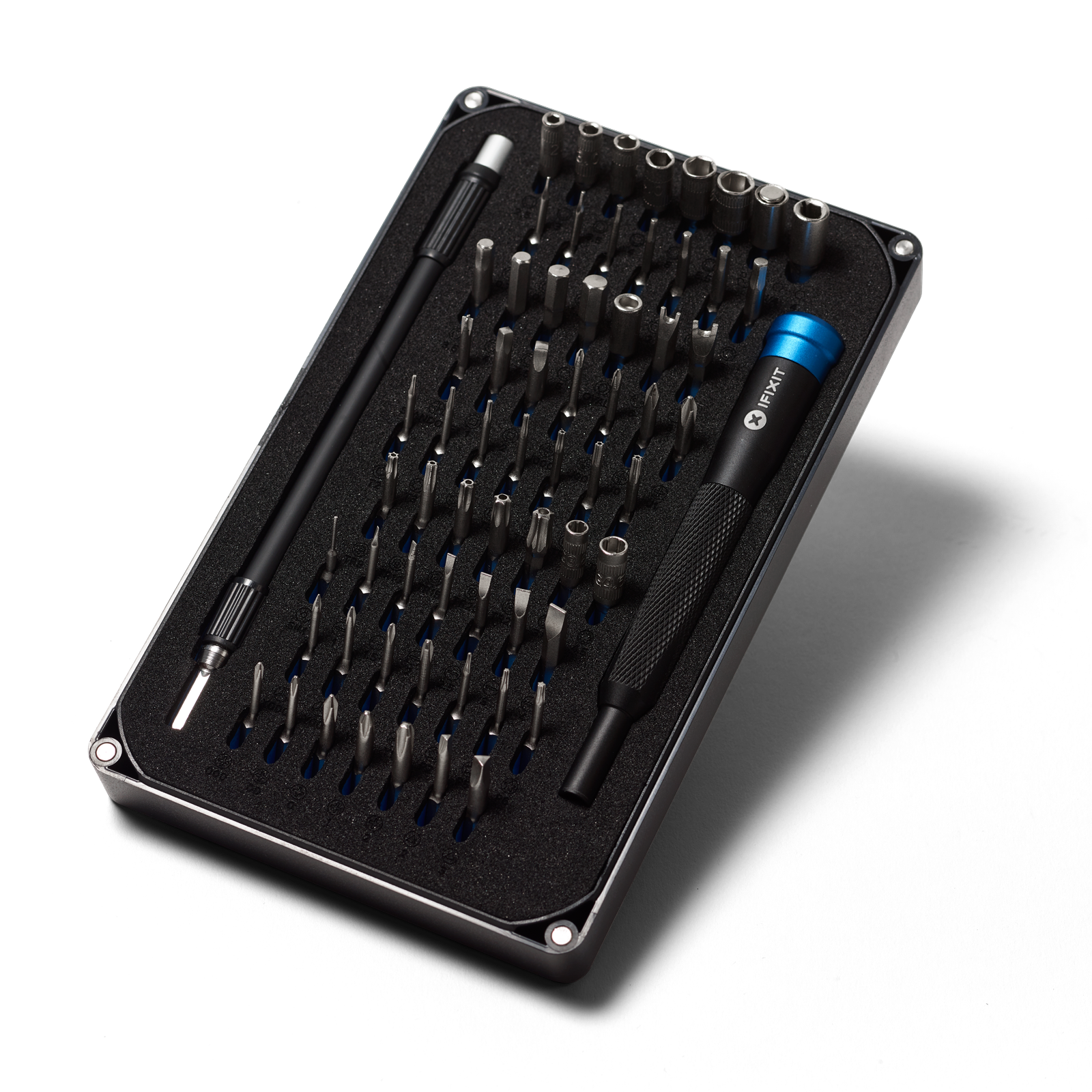
Regarding tools you don’t need anything special, i highly recommend a thin conical tip for the soldering iron if you will be using the 3d printed enclosure.
Schematic
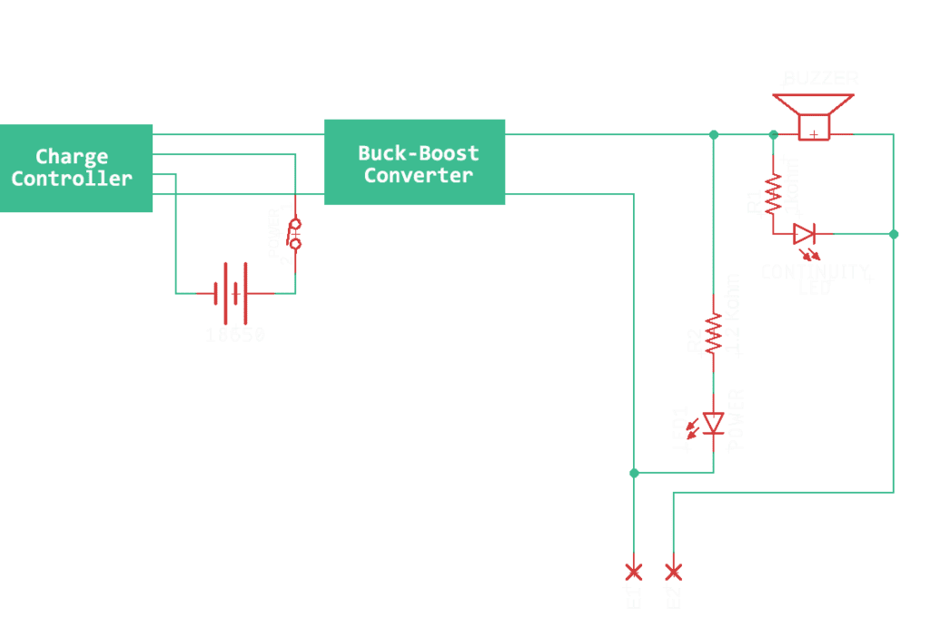
The schematic is quite simple. On the left part we have the battery connected to the charge controller with a switch in series to completely disconnect the battery when not in use, to prevent parasitic draw. We then feed the output to the input of the buck boost converter that we have set up to boost the voltage to 12V. The 12V output is used to power the indicator LED. The Continuity LED is connected in parallel with the buzzer. The test leads connect the buzzer and led to the ground of the buck boost converter.
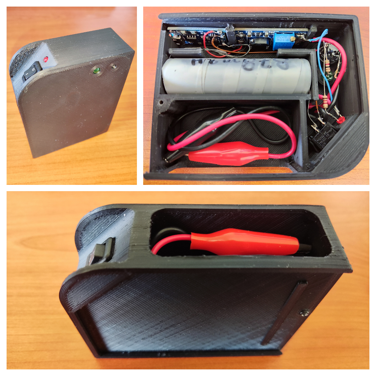
The case
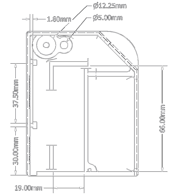

I designed and 3d printed a case in Autodesk Inventor, i added slots to hold the charge controller and the buck converter pcbs as well as holes where needed for the buzzer, LEDs and the switch. Depending on the parts that you choose they might not fit, that is why i have highlighted all the important dimensions on the diagram above. I also have added a compartment to store the test leads. I also recommend tying a knot on the test leads for strain relief. I have also made a lid that you can slide in and optionally secure with a small screw.
You can download from here.
Improvement ideas
- Strengthen some parts of the case, specifically the parts where the lid slides in. You might have better results if printed with PLA because it is more rigid, i printed it with ASA and the printer wasn’t properly calibrated at the time.
- UPDATE: Most of the failure points appear to be at the slots where the lid slides in, a thicker wall should help.
- Use a transistor to test continuity that way you can test cables with much higher resistance.
- Proper cable relief. While tying a knot is enough most of the time, it would be ideal to properly hold the cable to stop any movement at the connection point.
- Using some form of input protection is also a good idea.
- Some times when i open the switch it does not work, but if i try again it works normally. I suspect it is due to the charge controller or the buck converter because i have had the same issue when i used the same modules in a transistor tester.
- UPDATE: Found out where the issue is, the charge controller does not like turning its source on and off. This can be easily fixed by placing the switch on the output of the charge controller. The parasitic current draw should be too small to worry about.
- Maybe use better crocodile clips, like the ones that can pierce cables