DIY Open Source Chronograph
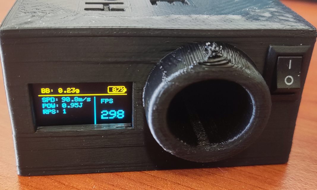
I got into airsoft recently, and I wanted a way to measure the BB’s velocity. The cheapest chronographs I could find were ~60-70€. I thought making one myself would be much cheaper and a good learning experience. The total cost was about 15€.
I tested it with an Army Armament R504, its specs sheet says it shoots at 300 FPS, I measured 298 FPS which is within the margin of error.
All the files for the project can be found on github.
Schematic
Below you will find 2 versions of the schematic. One using photodiodes and the other phototransistors. Initially I thought I ordered phototransistors, but they were photodiodes. Phototransistors are a better choice because you will need fewer components.
Components
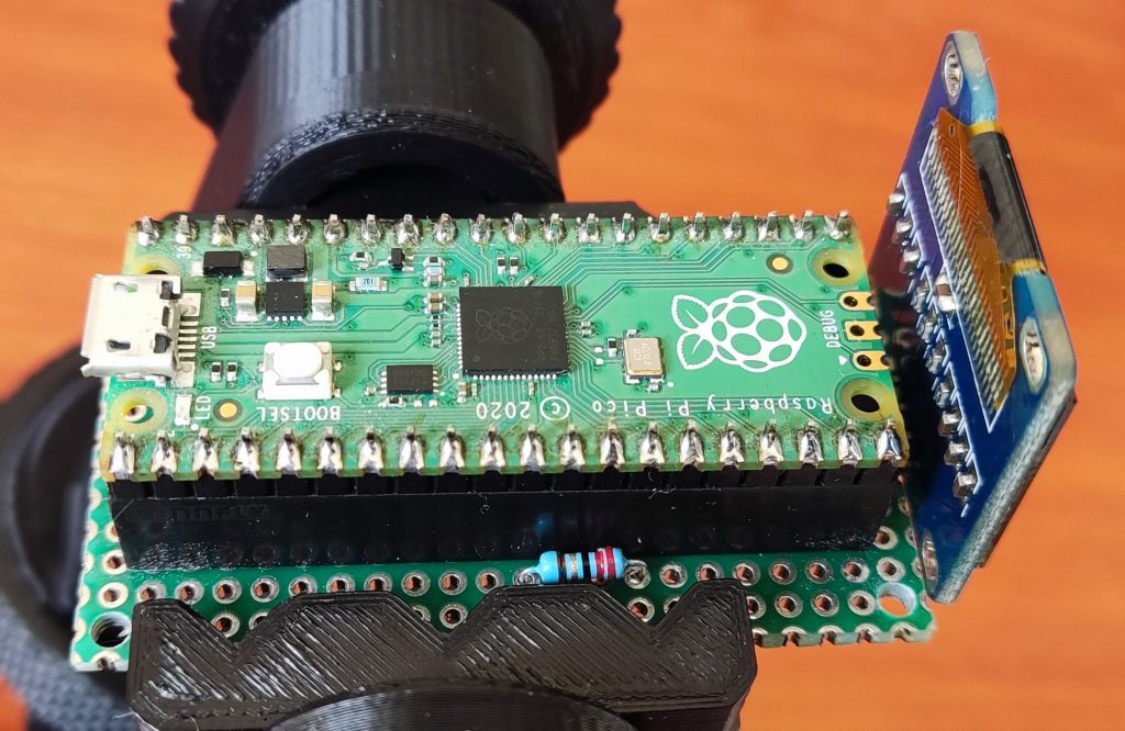
The pi PICO is an ideal choice because it is affordable, fast and most importantly it has 2 cores. Meaning, we can dedicate one core to do the measurements to increase accuracy. Also, I used the Arduino IDE to write code in c++ for faster execution (I love Python, but speed was essential in this case). The rest of the components are pretty standard, you will find a list below.
| Component | Quantity | Notes |
|---|---|---|
| TP4056 charge controller | 1 | I used the version with integrated BMS |
| 18650 battery | 1 | Used one from an old powerbank |
| Power switch | 1 | 10x15mm |
| SSD1306 128×64 I2C OLED display | 1 | I used a 2 color one, but any would work |
| Pi pico with headers soldered | 1 | |
| 4pin right angle male header | 1 | |
| 20pin female headers | 2 | |
| 5v buzzer | 1 | You might need a resistor, see below¹ |
| Tactile switches | 3 | 4 if you add the reset button |
| IR LEDs | 2 | You will also need appropriate resistors |
| 1A fuse | 1 |
1: Depending on the buzzer, you might need to add a resistor. The buzzer draw should be kept under 12mA.
Additional components with phototransistors
| Component | Quantity | Notes |
|---|---|---|
| Phototransistors | 2 |
Additional components with photodiodes
| Component | Quantity | Notes |
|---|---|---|
| photodiodes | 2 | |
| 2n3904 BJT | 2 | Or similar |
| 330Ω resistors | 2 | |
| 2.2kΩ resistors | 2 |
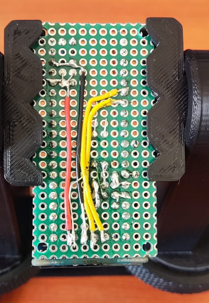
PCBs
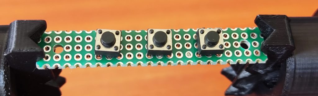
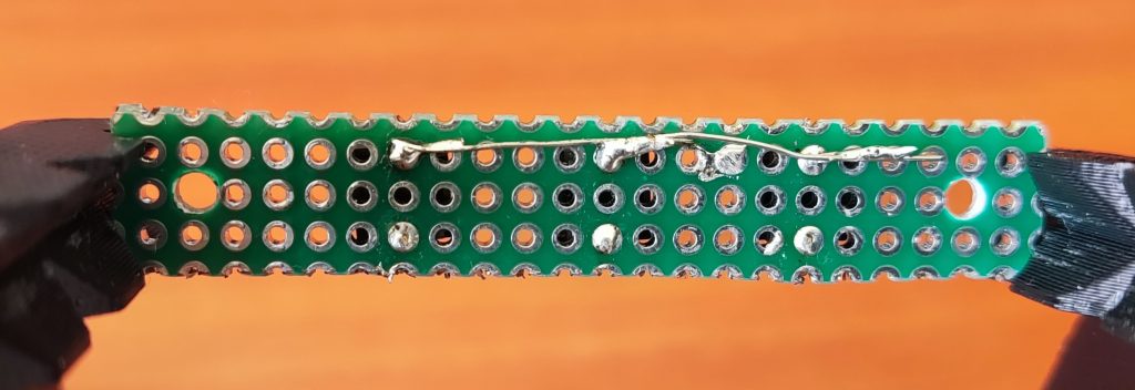
For the PCBs, I cut a protoboard to fit the enclosure. Below you will find pictures for size and layout reference. I had to trim the PCBs about ~1mm to fit in the enclosure. Designing a custom PCB in the future might be a good idea.
Buttons PCB
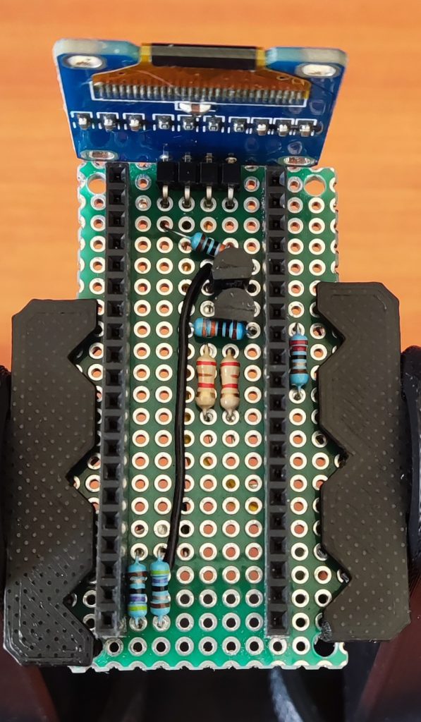
Main PCB
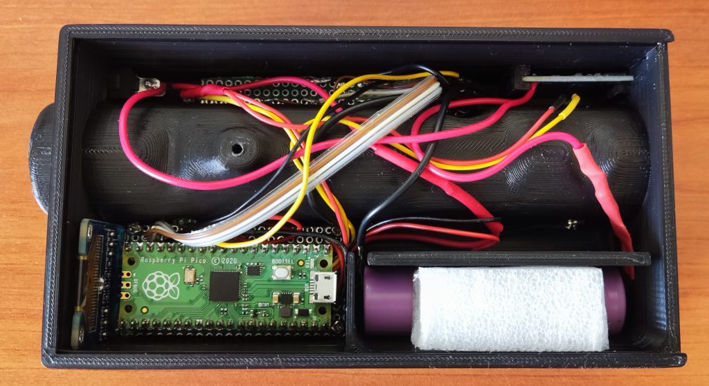
Enclosure
The enclosure is not perfect, but it works. It was designed to test the concept. I will design a better version in the future. The issues I have found and some future ideas are:
- The screen window is readable but not perfectly aligned
- A slot for a piece of plexiglass to protect the screen would be a good idea
- The PCBs had to be trimmed to fit
- A lot of wasted space
- The LEDs are not a tight fit and had to be glued
- The LEDs protrude slightly in the tube
- Charging port is not perfectly aligned, but it works
- The holes for the buttons had to be drilled 0.5mm larger for the buttons to travel freely
- The photodiodes detection range is a bit narrow, decent alignment is needed to detect BB (Maybe i should add multiple photodiodes on each side and do a “scan”)
Software
The software is simple and fast, I wrote it with c++ using the Arduino IDE instead of python for the higher runtime speed. The current button functionality in only for entering the “menu” and changing BB weight. But it is written in a way to allow future additions.